Home-made Gyro
The idea to design and make a home-brewed high-grade gyro for RC helicopter with the Heading Hold (Smart Lock, AVCS) feature had been occupying my mind for a quite long time. I thought about it as of an interesting and challenging engineering task. I had searched the WEB and found no any project like the one I wanted. Most of “experts” said that it is impossible to make a gyro with a performance like Futaba, CSM or other brands’ devices. As for me, I was actually concerned about only three main problems: to find an appropriate sensor, to choose an algorithm of control loop and to carry out debug and testing safely. So, here is a story how I have been trying to solve these problems.
Solving Problem No 1 – sensor
First of all, I did some research on Murata ENC-03J sensors I had got on hand. I measured their output drift over temperature change. The result can be seen on the plot:
Linear approximation (red solid line) shows that the sensor has a temperature dependency of about 3.4 mV for 1C degree. Taking in account that a sensitivity of the sensor is only 0.7 mV for 1 degree/sec of angle velocity, it’s clear that 1C temperature changing is equivalent to almost 5 degree/sec of angle velocity. As the “Heading Hold” feature requires velocity integrating, an angle error would be almost 300 deg for a minute. It was too big – I wanted an angle drift less than 5-10 deg for a minute. Therefore, it was clear that ENC-03 was not suitable for my purposes, even if I would use some thermo compensation or even thermo stabilization system. The idea to make a gyro ten times cheaper and ten times better than Futaba faded away :o) Finally, the problem number one was solved in very simple (but unfortunately not so cheap) way – I purchased the Analog Devices ADIS16100 sensor. The sensor seemed to be very suitable for me. And, by the way, I was impressed by their IMEMS technology http://www.analog.com/library/analogDialogue/archives/37-03/gyro.html
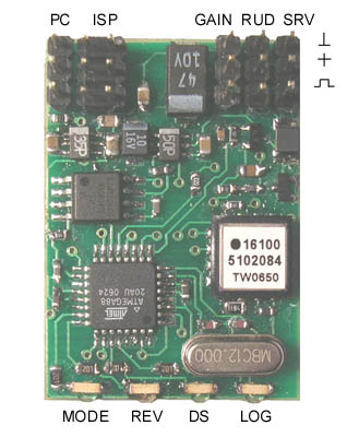
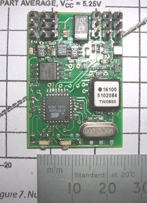
As ADIS16100 has built-in ADC, the schematic diagram turned out quite simple.Besides the obvious components, I added the 4Mbit EEPROM in order to make the solving problems 2 and 3 easier. Here is the assembled PCB. It has 38x27x10 mm dimensions and 6 grams weight:
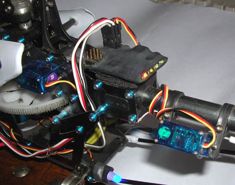
Installed on my T-Rex 450SA heli:
Solving Problem No 2 – control algorithm and parameters
It was obvious that in order to maintain yaw angle, device should integrate angle velocity and generate appropriate commands to tail servo using some PID regulator. Unclean were an optimal regulation law, its parameters and some details like what to do if a model on the ground was turned around and the angle error already exceeds hundreds or even thousands degrees. To make things more clear, I read Futaba and CSM gyros user manuals. Studying of their settings structure confirmed my guessing that they have proportional and integral loops as well as some damper system to avoid tail oscillation after fast pirouettes. Then I mounted my device on Raptor-30 RC helicopter together with Futaba GY401. At this stage, the GY401 did its main job and my device worked as fly logger: in real-time it had been measuring an angular speed, rudder pulse duration and the output of GY401 gyro. Data had been stored into on-board 8 Mbit EEPROM. After several test flights, I downloaded flight data to PC and tried to analyze them. As I could see from experimental data, to a first approximation GY401 could be considered as PD regulator of yaw angle (or, the same thing as PI regulator of yaw angle speed). It’s important that integral loop has a limiter with a value of several tens of degrees. The limiter prevents integrator from accumulation of too large angle error when control loop is open or can’t work properly (for example if a model was manually turned around on the ground). Then I tried to create my own mathematical model of PID regulator that would match data from GY401. Actually, I only needed to select the appropriate PID loop gains. Here is an example of behavior of GY401 and my mathematical model:
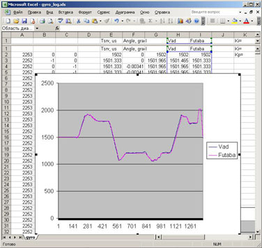
The such close matching was a good confidence that I was on the right way. So, I implemented a regulator in the firmware for Atmel ATmega88 microcontroller. (By now, I have implemented “Normal” and “Heading Hold” modes, remote gain adjusting, digital servo support, quick setup feature and RS232 support.) Everything was ready for a first flight.
Solving Problem No 3 – testing and debugging
I did not like the idea to make test flights on my Raptor nitro helicopter. Fortunately, at that time I had gotten small electrical Trex-450SA heli. It was much safer for first test flights. Moreover, it was possible to fly it at home. Thus, the problem No 3 just ceased to exist :o)
The very first flight was rather successful. I only reduced the gain a bit to eliminate some tail hunting and it flew well. I had been comparing the performance of my gyro with GY401 by subjective feelings and using flight logs. Both devices run quite similar, so I was pretty satisfied. As for yaw angle drift, I achieved better results: 1-2 degrees for a minute vs 10-15 degrees of GY401. By the way, the flight log feature turned on a very useful thing. I analyzed first logs to find out possible ways to improve the device performance.
By now, I have more than 50 flights on Trex-450 with my gyro and I am happy with it. The only bad thing happened: Futaba S3154 servo failed in fifth or sixth flight. I used it in DS mode and I do not know the exact reason of its failure - maybe bad quality of the servo. But I do not exclude some incompatibility with my device. Anyway, I replaced S3154 with a cheap analog HS55 and it works well for me. In addition, I have no possibility to compare my device with any top model like GY611. I just have no such device (as well as I am too bad pilot to fly extreme 3D).
Conclusion
It is possible to make a quite good and competing home-brewed gyro. Good luck!
© Vadim Kushnir (aka Vad64)